Shock Tuning Payoffs
Weight Transfer
As discussed in an earlier chapter, the load sensitivity of a tire means that, for any pair of tires on the same axle (or the same end of the car for an independent suspension) the tires produce maximum grip when both tires are equally loaded.
Unfortunately, physics conspires against us by transferring load from the inside tire to the outside tire every time the car goes around a corner. This moving around of load is called (perhaps confusingly) as "weight transfer" and is a major, if not the major issue of car setup. Because while we cannot stop weight transfer from happening, we can certainly influence how much weight transfer occurs, and where it occurs (in terms of the front or rear tires).
The "how much" controls the maximum grip we can extract from a set of tires, and the "where" controls which end of the car reaches the limit first (and under what circumstances) which controls the balance of the car. So we really care quite a bit about weight transfer, because it controls the maximum cornering power and what the car does when it reaches the limit.
It is worth reiterating that we cannot stop weight transfer. It is going to happen. The trick is in limiting its effects and, as much as possible, getting it to work for us.
It is also worth pointing out that there is some serious heavy lifting here. The concepts involved start out simple enough, but rapidly get very complex and by the end, we'll be operating at the limit of theoretical knowledge - there's a reason why it took so long to write this chapter....
Types of Weight Transfer
Weight transfer has two components:
- Unsprung Weight Transfer: This is the contribution to weight transfer from the unsprung mass of the car.
- Sprung Weight Transfer: This is the contribution to weight transfer from the sprung mass of the car, which itself is broken into two sub-components:
- Geometric Weight Transfer: This is the contribution to weight transfer from the lever that comes of the difference between where the suspension naturally wants the sprung mass to roll (the roll centre) and where the sprung mass naturally wants to roll on its own (the projection of thecentre of gravity onto the ground plane)
- Elastic Weight Transfer: This is the contribution to weight transfer from the reaction force of the springs and bars as they attempt to resist the spring mass roll.
These three components are additive, meaning that total weight transfer is the sum of all three components.
(Note that this is equally true fore/aft as it is left/right. I'm going to discuss lateral weight transfer for the most part, but everything applies the exact same way to longitudinal weight transfer for acceleration and braking. Drag racers take note!)
Unsprung Weight Transfer
This is the easiest component to understand, so we'll start here.
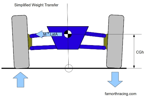
Imagine that we have a car with no suspension - like a kart. The kart goes around a corner. This requires a certain amount of lateral force (F) which acts through the centre of gravity (CG).
The force on the CG produces a rolling moment, the length of whose lever is the height of the CG above the ground (CGh).
This rolling moment is opposed by tires, the length of whose lever is the track (T).
So the total weight transfer is the lateral force (F) times the CG height, divided by the track (T)
And we usually break out the lateral force as the mass (M) times the lateral acceleration (LatA) so we get WT = M * LatA * CGh / T
If we have no articulated, sprung suspension, then we're done here - unsprung weight transfer equals total weight transfer. If we have a sprung suspension, it takes a bunch more work to account for the sprung mass rolling around. But the unsprung mass still contributes to total weight transfer, so for a sprung car, we change the formula so that the CG height is the CG height of just the unsprung mass (CGhU) - which for most cars is fairly well approximated by the height of the wheel center.
WTu = Mu * LatA * CGhu / T
From this, we can see that the ways we can reduce the amount of unsprung weight transfer are:
- Widen the track; and
- Lower the CG (though smaller diameter wheels, rotating the brake calipers to the 6 o'clock position, etc)
That theme - wider track, lower CG - will persist throughout the weight transfer discussion.
Sprung Weight Transfer
So now that we've accounted for the unsprung weight transfer, we need to account for the sprung mass.
As a first guess, one might assume that the sprung mass works effectively the same as the unsprung mass, so weight transfer would be the sprung mass (Ms) times the lateral acceleration (LatA) times the height of the CG of the sprung mass (CGhs) divided by the track - and you'd almost be right.
The problem is determining the length of the lever through which the cornering force acts. For the unsprung mass, it's the projection of the CG on the ground (the ground on the tires being the centre of rotation). But for an articulated suspension, the point around which the suspension wants to roll is controlled by the interaction of the suspension links and pivots with each other.
Think of it this way - if you push a door on the handle, it will pivot around the hinges. If you take the door off the hinges and stand it up on an ice rink and then push the handle, it will (assuming it doesn't fall over) pivot in place, somewhere near the centre (where the projection of the CG onto the ice surface is). The suspension works the same way as the door hinges.
The trick then becomes figuring out where that pivot point - the roll centre lies. And that's where things start to get REALLY complicated.
Firstly, because locating the roll centre is really not a straightforward process. Secondly, because there is an intrinsic amount of weight transfer that is a function of the difference in height between the roll centre and the ground (the pivot point for the unsprung mass) and a second component based on the difference in height between the height of the roll centre (RCh) and the height of the CG of the sprung mass.
So to help calculate these sub-components, we call the first the Geometric Weight Transfer and the second the Elastic Weight Transfer.
Some textbooks refer to the Geometric Weight Transfer as "jacking force" and it can be helpful to keep that term in the back of your mind - because based on where the roll centre lies, that jacking force can be positive, negative, or neutral. And to further muddy the waters, the roll centre can (probably will!) move as the suspension articulates!
Breaking these down into equations, we get:
WTg = Ms * LatA * RCh / T
WTe = Ms * LatA * (CGhs - RCh) / T
Now if you pay attention to these equations, you can see that the location of the roll centre is really very important:
- If the roll centre height is on the ground (0) then the geometric weight transfer is zero (no jacking force) and the elastic weight transfer is maximum;
- If the roll centre height is on the CG, then jacking force is maximum and the sprung mass won't roll (the car will try and flip over the outside tire);
- In between these two extremes, you get an intermediate result; and
- If the roll centre is below the ground, you get "anti-jacking";
So clearly, we need to figure out where the roll centre is.
The other interesting aspect is that while we can only influence the geometric weight transfer via the location of the roll centre, all of the elastic weight transfer acts through the springs and bars. The amount is determined by CG height, track width, and roll centre height, but where it goes is a function of the roll resistance of the springs and bars. On the simplified, one-end-of-the-car model we're looking at now, this has no effect, but when we get to a full-car model later on, this becomes very important. For now, just remember that the elastic weight transfer portion is taken up by the springs and bars.
Locating the Roll Centre
Locating the roll centre is one of the nasty bugaboos where real research is still being done. For years, you calculated the location of the roll centre by drawing a scale model of the suspension, then drawing vectors through contact patches and along suspension members until you found where certain vectors intersected. This was known as the geometric roll centre method and it works well enough - but not perfectly. Particularly, it produces some very weird results if the roll centre moves through the ground plane that don't necessarily translate into the same observations on the car.
A newer method is called force-based roll center which (as a gross oversimplification) attempts to model the car suspension, feed the observed forces into it, and see where it rolls around. This appears to be the better way of doing it, but it is vastly more complicated to work out.
The whole "work out where the roll centre is" problem is very much a "Doctor, it hurts when I do this" problem. Rather than trying to work it out for yourself on paper, or with a CAD program, or whatever, it is far, far, FAR simpler to use a suspension kinematics program like WinGeo to do it for you. The latest version of WinGeo will do both geometric and force-based roll centre calculations for you and just spit out the roll centre height. Do that. And note that this is done for both front and rear suspensions.
Don't try and figure out the roll centre location by hand - buy WinGeo and have it do it for you.
The 4-Wheel Model
So now that we have the roll centre height for the front and rear suspensions, we can start stringing all this stuff together.
The first part is that we need to break up each component of weight transfer to its front and rear parts - so track (T) becomes (Tf) and (Tr) for front and rear track. We assume that CGh is the same front and rear (it's too hard to measure separately) but the proportion fore/aft is the front/rear weight distribution, so if the car is 60% nose heavy, Msf = Ms * 0.6, etc.
Done for unsprung weight transfer and geometric weight transfer (on both ends of the car) you now see how much weight transfer you have that you have little control over (outside of track changes, CG height changes, or roll centre height changes - tough to do on a production based car, slightly easier on a formula car).
What's left is the elastic weight transfer, and this you DO have some control over. Not in terms of amount, but in location. The total amount of elastic weight transfer will act through the springs and bars, so by changing the relative strength of the springs and bars front to rear you can change how much of that total weight transfer goes across the front axle and across the rear axle. By tuning that, you can control which end of the car loses grip first and accordingly, the balance of the car.
Note that all this needs to take into account the motion ratios of the springs and the static weight distribution of the car - all of this is accounted for in the Dynamics Calculator.
Springs vs Bars
All of the elastic weight transfer must be taken up by the springs and bars - that's where it goes. The overall strength (in terms of roll resistance) of the total of the springs and bars determines the final roll angle of the sprung mass, and the relative strength front to rear determines balance. But the natural frequency of the suspension (which is calculated springs only) determines bump compliance, damping forces, and bump-related grip. If the springs get too stiff, then the wheel loses bump compliance and the car starts skating. So you choose springs to produce the natural frequency that gives you enough bump compliance, (normally not much higher than 2.5Hz for a non-aero car) and if those springs aren't enough to keep the roll angle under control, you have no choice but to go to bars.
If you are in this pickle (as will be most production-based cars: high CG, heavy sprung mass means lots of elastic weight transfer to absorb) you set the front springs for NF, the rear springs slightly stiffer (to keep the car flat as bumps move fore to aft; the rear must react a little faster). Bars you size so the total resistance gives you the roll angle you want but the relative resistance keeps the balance intact. For the typical nose-heavy production car, this means a stiff front bar and a soft rear bar. Done properly, you can dance on understeer/oversteer with small changes to the rear bar (and the rear bar is usually way easier to reach).
Ideally, you want no bars at all - while they don't create any extra weight transfer (the total amount of weight transfer is a function of track, CG height, and roll centre location) they can only add a larger proportion of roll resistance at that end of the car, which means increasing that end's share of the roll resistance, which in turn means "unsticking" that end of the car.
As a general rule, it is better to balance a car by figuring out ways to make the sliding end grip more rather than making the grippy end grip less. If the root cause is weight transfer, you may not have much choice - but the first instinct should not be to reach for the thicker bar.
A formula car can have bars the size of pencils totally as trim devices. For production car, getting the CG low and the sprung mass down can really pay grip dividends IF you remember to make the bars smaller as the car gets lighter.
Tuning the Roll Centre
I largely handwaved away mucking about with the roll centre as a tuning tool in this section, because for 95% of the readership, you won't have any way to change it. Limited by either the rules or by the complexity, the roll centres (front and rear) will be what they are, and the only really way to change their location will be via ride height changes via spring preload.
So while it is very important to understand where the roll centres are and what they are doing, changing them as a tuning tool is probably outside the scope of most production-based cars.
However, it is probably worth mentioning the merits of playing around with the roll centres.
Earlier, I mentioned that weight transfer occurs effectively instantaneously. That is, strictly speaking, not entirely true. The unsprung and geometric components of weight transfer do occur, for all intents and purposes, instantly. The elastic component of weight transfer occurs somewhat later, and any inertial effects (rotational inertia of the sprung mass) will arrive still later and then go away.
Because the geometric component gets there earlier, and because it is in theory tunable via changing its height and path, one can adjust when the weight transfer arrives by changing the location of the roll centre. A higher roll centre produces advances weight transfer, and a lower roll centre retards it. This, all else being equal, means a higher roll centre improves turn-in, and a lower roll centre slows turn-in.
But much like toe out can improve turn-in, too high a roll centre can cause other problems. If the roll centre gets as high as the CG, then the springs and bars won't compress at all....
For most, this is a purely academic discussion. I suspect that an autocross car may want a slightly higher roll centre than the same car on a road course. There is also a school of thought that says that the ideal place for the roll centre is above ground, but as close to the ground as possible. I suspect that the best answer is an adjustable roll centre that starts there, but allows tuning upward to see what happens.
My official take on roll centre tuning is that given the difficulty in changing it in most cases, don't get wrapped up in worrying about it. You do need to know where it is though, and that's where software like WinGeo can prove invaluable.
Learned something?
Help keep ATW online!